10-11 October 2009:
When the car arrived, one of the first things I noticed was that the turn signal stalk on the steering column was missing. This would explain why there was a turn signal stalk amongst all the spare parts that came with the car. Closer inspection of the steering column revealed that the stalk had actually been snapped off. How one could snap a blinker stalk off the steering column is beyond me and I guess I will never know how it happened. The broken surfaces were all rusty indicating that it had been broken a long time.
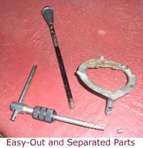
The first task was to try and remove the broken stump from the switch plate. I was hoping that I would be able to remove the switch place complete with stump and put it in the vise and then work out how to get the stump out. So I removed the steering wheel which obviously hadn't been off in a very long time because I bent the steering wheel puller in the process. The Mercury is neat in that you don't have to disassemble the horn ring and contacts to remove the steering wheel - it all comes off as one assembly. Unfortunately when I got to the switch place I found that the broken stalk stump was actually locking the switch plate to the steering column collar so it would have to be removed in situ. To achieve this I gently drilled into the stump using progressively larger drills until I could get an easy-out into the hole but no amount of turning would budge the stump. By this time it was late and so I drenched it with WD-40 and left it overnight. In the morning the easy-out worked a treat and out came the stump along with the switch plate ! While the steering column was disassembled I tested the blinker circuit by manually actuating the electric switch. It was dead as a dodo. Something else to look at once the broken stalk was fixed.
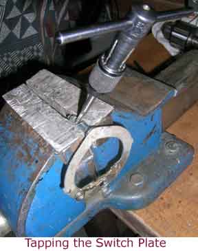
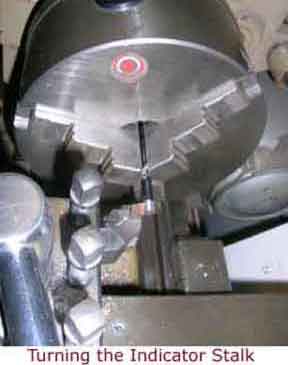
The easy-out had ruined the thread of the switch plate and also the broken blinker stalk had no thread left on it, so it was time to go over to Dad's workshop and do some machining. The old thread must have been 3/16" (4.8mm) but the next Imperial thread size up is 1/4" (6.4mm) which is a big jump. So I gritted my teeth and tapped the switch plate out to a 5mm metric thread, however, testing with 5mm bolt showed that there was insufficient thread to tighten against. So I drilled the switch plate out and tapped it with a 6mm metric thread. This time a 6mm bolt tightened up nicely. Next I mounted the blinker stalk in the lathe and turned a short length of it to the required diameter and then cut a thread on it with a 6mm die. Screwing the new thread on the blinker stalk into the new thread on the switch plate gave a really snug fit. Job well done !
Now time to look at the electrical circuit. The blinker circuit runs as follows: 12V to the fuse, then to the flasher can, then through the switch and then to the front, rear and instrument panel lamps. It's a little more complicated than this because the brake light circuit also flows through the blinker switch. This is because the brakes and blinkers use the same filament of the rear lamps. So pressing the brake without the indicators on means that left and right lamps glow continuously. Pressing the brake with the indicator switch set to turn the right disconnects the brake voltage from the right hand lamp and instead connects the indicator voltage to it, so it flashes, but leaves the brake voltage connected to the left hand lamp so it glows continuously. Braking with the indicator switch set to the left is the reverse of this. Shown below is a diagram of the circuit.
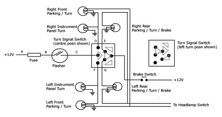
First test was whether connecting +12V at points D-E-F-G caused the lamps to light. This is a good test because flasher cans often don't work if the load is insufficient. This test showed that the front and indicator lamps were all working but neither rear lamp. Removing and inspecting the lamps in the back showed that neither was earthing. The lamp fittings are an unusual type of dual-layer bayonet fitting where they insert into the lamp housing, one part is plastic and one part is metal. The two layers of the bayonet need to have their pins aligned, then they are inserted into the lamp housing and rotated 90 degrees. When they are rotated, the pin of the plastic part of the bayonet remains stationary and the pin of the metal part rotates and then makes contact with the metal housing thereby earthing the fitting. If the fittings are not removed or inserted properly, the pins become misaligned and the fitting doesn't earth which is exactly how I found both the lamps in my car. Aligning the pins and inserting the lamps properly into their housings brought the rear lamps to light. However, this still didn't make the blinkers work...
Connecting +12V at point C and working the blinker switch showed that the switch was working fine. At this point I suspected the flasher was at fault because flasher cans don't last forever, however, putting a known working one in the circuit didn't change anything. At this point I checked the line voltage at points B-C and all showed 12V. However, to check the voltage I had to disconnect wires. When I reconnected, and tested the lights, nothing would work. Finally I decided to check the voltage at point C while the switch was in the on position and it was zero volts. With no load 12V and under load 0V. What was happening ? Couldn't be a short circuit because nothing was getting hot. I decided to use a dummy globe as a test load and applied the load at point A - fine and then at point B - nothing. It had to be the fuse section (I had already checked the fuse!). Was the fuse panel full of more Arizona dust ? Was it corroded, damaged ?
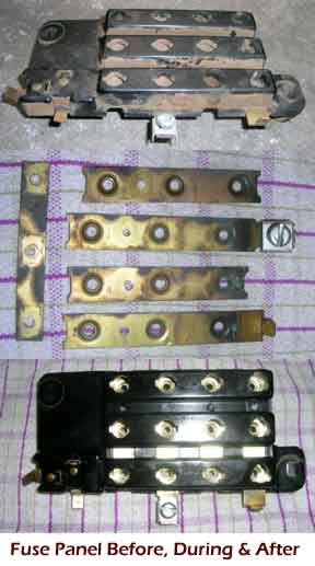
The fuse panel is rather inconveniently located up under the dashboard at the top of the brake pedal anchor. It's a panel of 12 sockets that bayonet-type fuse holders are inserted into. Three of the holes are for constant 12V and the remaining nine are for 12V only when the ignition key is in the 'on' or 'accessories' position. This is also where the flasher can is located. I disconnected all fuses and wires and removed the fuse panel. Looking into the spot where the turn signal fuse was located it was easy to see what the problem was. The brass contacts were green with corrosion. Clearly when connected, enough current flowed to register 12V on the meter but under high load, as in when the lamps were connected, the resistance of the connection was too great and the voltage dropped to zero. The fuse panel is a large bakelite assembly with strips of brass located under lugs at the back. When the fuse holder is located in a hole, the end of the fuse contacts the brass strip, completing the circuit. Unable to satisfactorily clean the brass contacts through the holes I drilled out the brass rivets and removed the brass strips. I polished them all with steel wool, coated them in a film of WD-40 and riveted them back in place. I reinstalled the panel back into the car and connected all the wires and fuses. Lo and behold the indicators finally worked !
That was certainly one long and tedious process to get something as simple as the indicators to work. Not just one but three things were stopping them from working.


